Photo

Photo

Monday, February 29, 2016

Arduino Introduction

On Friday, we learned about the basic uses of the Arduino microcontroller, which used aspects of both electronics and computer science. My partner, Jiaming, and I have a little experience with both of these topics since we're both currently in PHY 108, where we're currently working on circuits and often use Python for physics animations. Python isn't exactly the same as the C++ that the Arduino, but the way of thinking necessary for computer science is similar.

Potentiometer
Tools we used:
breadboard – where we build
our circuits
resistors


LED – Light Emitting Diode

Applications:
  • For the first project we started with a basic example program and had to figure out why a delay time of 10 leaves the light on constantly. Through this exercise, we learned that the time unit for the program is milliseconds and the delay of 10 ms is so small that the human eye can't register it, which is why it appears to be on continuously.


  • For the second project, we had to create a blinking light pattern with at least three different lights, while using the delay function. We chose a pretty simple pattern, but it could easy made longer and more complicated by altering delay times and adding in more on/off commands.


  • For the third project, we turned the difficulty up a notch; we had to use the potentiometer to change the delay time of a blinking LED. A potentiometer has fluctuating resistance that is dependent on the degree of rotation of a nob. It makes changing values like delay times, in this exercise, really easy. Potentiometers are really useful tools!


  • For the fourth project, we had to figure out a way to create a 3 LED light pattern without the use of the delay function. Instead, we used multiple if - else statements to accomplish the task. This was definitely the hardest of the four tests. This activity definitely taught us the importance of careful bracket placement. We accidentally left the time update code outside of the while loop which created quite a predicament.


Reflections:
Learning how to use the Arduino wasn't extremely difficult. The circuitry wasn't very difficult although it took some adjusting to get use to the non bread board part of the circuit. The programming portion is very similar to the C++ that I learned previously in high school, so for me it was less of learning something completely new and instead, learning new conventions for things I've learned previously. That being said, this is just day one with Arduinos and I anticipate the programming portion getting a lot more difficult. Things that I struggled with was definitely the little things – making sure the program is set to the correct port, spelling words correctly, putting the brackets in the correct place, and the ever pesky semicolons.


Sunday, February 28, 2016

Lego Racecar

For this project we learned how to use gear drives and were tasked with building a lego racer that would compete in a 4 meter dash. The lego racer is powered by a single motor with high speed, but low torque and has to carry a 1.0kg weight across the finish line.

My partner, Katrina, and I started by creating random gear train ratios to get an idea of what would be appropriate for our racer. Here are some examples of gear trains that we built and tested.

1:25
24:40 , 8:40 , 40:24 , 8:40
1-9
8:24 , 8:40 , 40:24
1:125
8:40 , 8:40 , 8:40
1-15
8:40 , 8:40 , 40:24


Once we made a few options, we went ahead to build the rest of the car, so we could begin testing out the ratios. Katrina focused on figuring out where to put the wheels and where to put the motor and PicoCricket. We originally felt that we would need a way to keep the weight from rolling off and given a weight that would sit flat, we decided to build a sort of container to put it in, so that it would be able to attach to the rest of the cart.
Katrina is troubleshooting
the motor

Regarding the wheels, we decided to use three wheels instead of four thinking that less wheels would mean less friction with the ground, especially since the motor was only driving the front wheels. For the front wheels, we decided to use the biggest wheels we had available because that meant that for one rotation, the wheel with the larger circumference would travel a farther distance. The back wheel, whose only real purpose is for support, we decided to used the smallest wheels available to use because a smaller wheel yields less friction.

Our first iteration:
The Tank (1:125)
Here's the structure that
I worked on
Our first iteration using a 1:125 gear ratio was a flop. It took the lego racer about 40 seconds to go from start to finish. As you can see from the picture, the lego racer looks quite formidable and would probably do better in a lego racer monster truck rally than in a competition for speed. So it was back to the drawing board for us.

We did a lot of testing and recorded times for the gear trains we built earlier and soon came to a conclusion that a 1:15 gear ratio would work to best. While the other gear ratios had higher torque, they didn't have enough speed. We needed to find the ratio that would allow the lego racer to have enough torque to move across the carpeted race cart, while maximizing speed and the 1:15 gear train do just that. It was also during these trials that we realized the less gears we used the better because each gear added, added on friction to the system.

We also realized that it would be in our best interests to make the cart thinner and move the wheels closer together. The further apart the wheels were from one another and the slower the cart would be. What we decided to do, in order to make the lego racer thinner, was to make parts of the gear train vertical, therefore preserving space. This would also allow us to drive both of the front wheels on one axil instead of two, which definitely helped to reduce gear friction.

Originally, we were hesitant to make the cart to tall because we were worried it would tip over more easily. However, we remember that since we are going along a straight course, height won't be a huge factor, now if this lego racer was taking laps in a circle, this might be something we want to consider.

We also decided to do away with the container we encased the weight in. Since we had two bigger wheels in the front and one small one in the back, by placing the weight in the front, gravity would keep the weight propped up. Therefore, we don't need the container that added a lot of weight to our cart (although it did look pretty cool...).

We struggled to to create a 1:15 gear ratio with just four gears because of spacing issues, so we ended up having to use six gears instead. This definitely added a bit more gear friction and slowed us down during the race.

Underside
Front view 
Our final iteration

Come race day our lego racer definitely wasn't the fastest clocking in around 12 seconds, but that was still a pretty big improvement from our first iteration. Given more time, we would definitely try to find a way to recreate the 1:15 gear ratio with only 4 gears. That is likely the leading cause of why we took so much longer than other teams. From there, we would then also consider ways to minimize the weight on the cart, but the gear train would definitely be the priority.


Monday, February 22, 2016

Well Windlass

Our challenge for this assignment was to create a well windlass – a device that goes over a well and can lift a “bucket of water” via a crankshaft.
http://waterbuckpump.com/wp-content/uploads/
2014/01/250px-Wheelaxle_quackenbos.gif
In our case, we had to lift a 1 liter bottle of water so that the top 10 cm of the bottle is lifted above the tables. The success of our project depended on the windlass’ ability to lift the bottle without it shaking or breaking the device as well as it’s ability to lift the bucket within a time frame of 45 seconds. To accomplish this task we were given a 50 cm Delrin rod and limited to 500 cm^2 of Delrin sheet for the final prototype.
The first issue my partner, Marissa, and I tackled was the issue of how to lift up the bottle without breaking the device. With a limited amount of Delrin rod, we had to find some way the maximize it’s usage. We knew that we had to cut the rod up and create a circular shape for the string to wrap around, but we were concerned about whether one rod would be able to withstand the weight of the bottle. What we decided to do was to cut the rod in three equal length pieces and to keep them together in a bunch because we felt that together as a thicker rod they would be able to withstand the force of the bottle. To combat the issue of whether the bottle would be pulled up in the time required, we decided to wrap the rod in a outer shell that would increase the circumference of the rod. We decided that the best shape for this shell would be something that closely resembled a circle and ended up creating a hexagonal shell whose sides would be piano wired together.

Having agreed on what to do with the rod, we decided to tackle the
issue of what to do with the rest of the structure. From previous experiences in physics based bridge building games, I know that triangles are much stronger than any other polygon because, geometrically, the angle of a triangle is determined by it’s opposite side length. In comparison, the angles of other polygons can be changed/altered without changing the length of the sides. So in our structure we decided to support the windlass on a triangle with another triangle to support it from the side, creating a variation on a right angled pyramid.

From there, we attached the structure to a square base because we wanted to maximize the contact
area of the windlass with the table. As added protection against the device slipping or sliding, we decided to create a piece that would wrap under the table. We added multiple peg holes so that it could be adaptable to varying table heights.

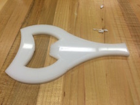
The last piece to our prototype was the handle. We didn’t want to make an extension of the rod into a handle because we know that a lever would make rotating the rod much easier. To create a lever we decided to create a piece that would slip over the rod and connect the actual handle piece to the device.


Our Good Friend
the Drill Press
Building the Hexagon's
Sides on SolidWorks
The hexagonal shell didn’t turn out exactly like we would’ve like because the drill bit wasn’t long enough to drill through the entire length of the shell. So instead, we made holes and both ends of each side. As a result, the holes didn’t line up as well as we hoped. However, the shell served it’s purpose, but it wasn’t as uniform or as nice looking as we had anticipated.

After creating the first iteration of our prototype, we realized that through some mathematical error, we ended up usually about twice the amount of delrin that we were allowed. :( Oops. So for our second iteration of halved the size of the clamp piece that extends under the table and made cut outs on the pieces, wherever, it was possible. The only thing we kept the same was the hexagonal shell.

Melissa and I really scrambled to create our final piece as a result of our mathematical error. Since
we didn’t realize our mistake until Tuesday the 16th, we only had three days left to reprint everything and troubleshoot. We didn’t end up being able to fix everything, but we did manage to make a few edits to our design. For stability, we ended up added two more pieces of support halfway down the triangles because the triangles were leaning inward a little. We also put in some piano wire at the base of the triangle in order to ensure that the structure wouldn't topple during use. While our windlass succeeded in lifting up the water bottle, the rod was prone to falling out of the handle. If we had more time on this project, we would have heat staked the rod to the handle so that it wouldn't be able to fall out. Since we forgot to take into consideration the table's legs when taking measurements, we were only able to use one of the stabilizers that held the windlass in place, to fix this we would definitely remeasure and made edits to the piece that wrapped under the table and heat stake the rod to the handle.
Our final design post presentation

Watching the other group's presentations was really interesting. Unlike in the bottle opener assignment there was a far greater variation in creations. There was no one way to create a windlass, although some designs were definitely greater than others. If given the chance to produce a complete overhaul, I would definitely rethink the usage of the rod's and try to produce a larger circumference by spacing out the rod's since it seems our initial worry that the rods by themselves wouldn't be enough to support the weight of the bottle.

Overall, our windlass used up about 540 cm^2 of Delrin, which is above the limit by 40 cm^2.

If we could do another rendition of the windless, we would first need to shorten the piece that locks in under the table because we originally forgot to account for the table’s leg. That would take off about 5 cm^2, bringing us to a new total to roughly 535 cm^2. We could use less Delrin by halving the part that slips under the table. That would take off about 60 cm^2 of Delrin, which would bring our new total to roughly 475 cm^2 of Delrin. Finally, we could also cut a hole out of the center of the handle’s, which would then definitely drop our total Delrin usage to around 470 cm^2.

My partner and I really struggled with this project as a result of our mathematical error, which is rather unfortunate. We both learned a pretty big lesson from this assignment – if we were more careful during our brainstorming process or had double checked along the way, we could’ve avoided a lot of stress and tears. Regardless, I think it's pretty cool that we managed to design and construct a windlass within two weeks!


Sunday, February 14, 2016

Mechanisms – Worm Drive Mechanism

For this assignment we looked at mechanisms that allowed for rotational movement to be translated into vertical or horizontal movement. I thought the worm and gear mechanism was really interesting.

This mechanism has been around for many centuries. The earliest records of the use of the worm drive date back to Pappus of Alexandria, a Greek mathematician, in the 3rd century AD. The name of the mechanism comes from the fact that it utilizes a gear and a worm screw.
This mechanism is also known as an endless screw because there is no end to the number of 360 degree rotations it can make. As the worm drive spins perpendicularly to the gear, its tread lines up with the teeth of the gear and cause the gear to rotate.

The worm screw spins at a faster rate than the gear does, which allows the gear to create more power. This happens because speed is inversely proportional to power. It is also important to note that rotating the gear does not cause the worm screw to spin, so in order for this mechanism to work, the worm screw must initiate the movement.

The worm drive is most commonly used in elevators because, as I mentioned above, the gear cannot turn on the worm, so when used in elevators this mechanism doubles as breaks – preventing free fall from occurring. Worm drives can also be found in automobiles, conveyor belts, and various other pieces of machinery.

I thought this mechanism was really interesting because even though it has a relatively unimpressive appearance, it has some pretty useful features. In addition to its locking/breaking abilities, of which no other arrangement of gears can claim, the worm gear can also be used for gear reductions, the reduction of revolutions per minute.
Gear reductions allow for machinery to be much more manageable. However, gear reduction can be achieved with various other methods of organizing gears and is therefore not unique to worm drives. In addition to the above, I thought it was very interesting have this mechanism functioned on the basis that the gear and the screw were perpendicular – not something I really imagine when I think of gears.


http://kmoddl.library.cornell.edu/model.php?m=16
http://kmoddl.library.cornell.edu/model.php?m=492
http://kmoddl.library.cornell.edu/model.php?m=572
http://www.electrolift.com/the-worm-gear-advantage.php
http://mechteacher.com/worm-gear/

Sunday, February 7, 2016

Fastening & Attaching

On Tuesday, we spent the class visiting stations set up around the classroom in order to learn about the tools for our next project. My partner, Rachel, and I decided to start with the Drill Press, Arbor press, and piano wire station first.

At this station, we learned how to use piano wire to fasten two pieces, that fit like puzzle pieces, together. The Drill Press puts hole/s in the piece and then we use an arbor press to push the piano wire into the piece. This combination is what fastens the two pieces together. This method of jointing allows 270 degrees of rotation. However, it is difficult to line up the pieces so that the joined pieces allow for that full degree of motion. If not enough of a gap is left between the pieces, the edge of the pieces will hit one another, preventing the range of motion that is a benefit of this method of attachment. As a result, this form of attachment requires a lot of trial and error. The Drill Press/Arbor Press is very useful for creating a connected piece that is able to rotate.

The next station we went to was the heat staking station. This machine was pretty easy to operate. Once the pieces were aligned underneath the nozzle, the machine was heated up to it's desired temperature, 450 degrees, it is then lowered and held on the piece. When the piece is sufficiently melted, and as a result attached, the machine is turned off and a stream of gas is blown onto the nozzle and piece to cool it down. The attachment created by the thermal press is permanent, which could be both a benefit or a drawback depending on what you need it for. The use of the thermal press is best for creating a permanent connecter between two pieces.

The last station we went to was the slots/peg station. At this station we took the measurements of rods, bushings, and pegs to get a better understanding of the degree of accuracy of the laser cutter. We also had a chance to see how slots and pegs could be used to join together two pieces. The slot and peg method, is probably the easiest of the above methods because once the pieces are printed, to assemble, you just snap the two pieces together. If the measurements were done correctly, correctly factoring in the accuracy of the laser cutter, the pieces should fit snuggly together. This method does allow for the pieces to be attached and detached repeatedly. After too many repetitions, however, the fit becomes looser, so the slot peg method isn’t great for projects that require connected joint that opens and closes repeatedly.

As I mentioned earlier, at the slot/peg station we also took the measurements of various bushings and pegs. The bushings came in three different fits that were all relative to the rod it was been fitted around. All measurements were made with the use of a caliper, a device that measures the distance between two opposite sides of an object. In the data below I took 3 trials for each measurement. The data from these recording is where the +/- # value comes from – the variation in the data.

The found that the rod had a diameter of 0.250 in. +/- 0.001. In comparison, the loose fit bushing was roughly .0015 +/- 0.001 in. larger in diameter. The snug fit was roughly 0.0025 in. +/- 0.001 in. larger in diameter and the pressed fit was approximately .0009 in. +/- 0.001 larger in diameter.
The tighter bushings, because they don’t move around easily across the rod, would be really good at acting as barriers that prevent other objects on the rod to slide all across the rod as well. These tight bushings are really similar to shaft collars which have a similar function.
The looser bushings seem to work similarly to spacers – creating distance between two objects that shouldn’t rub against one another (e.g. metal against metal).

The peg had a thickness of 0.1260 in. +/- 0.0005. The loose fit had a height 0.145 in. +/- 0.002. The snug fit had a height of 0.1350 in. +/- 0.0010. The pressed fit had a height of 0.1195 +/1 0.004. It is also important to note that for the peg/slot measurements we were able to compare the recorded data with the height that was specified in solid works. I found that across the board, the data that I measured had a discrepancy of approx. 0.01 in. for both the loose and tight fit slots/pegs. This discrepancy seems to be a result of the laser burning away more than specified because the heat of the laser melted away parts of the delrin that wasn’t meant to be melted away, during the creation of the part. It could also be a result of use throughout the day. The pieces were repeatedly and forceful being shoved into one another, which could also explain the discrepancy between the intended value and the actual value.

This is definitely something important to keep in mind when working on our Windlass assignment. It is better to make the slots slightly smaller than intended, subtracting the 0.01 in. discrepancy that I saw in my measurements (or make the pegs slightly bigger), to ensure that the peg/slot pieces will continue to do their job and hold each other in place. In general practice, this discrepancy created by the laser cuter should be remembered especially when dealing with pieces that require very precise measurements.

Bottle Opener


For our first project, the class was tasked with creating a working 2-D bottle opener. My partner, Rachel, and I started by brain storming and drawing a series of possibilities. Both of us were a bit rusty when it came to brainstorming, but we bounced ideas off of one another and drew everything that came to mind. Here are a few of the ideas we came up with.


After talking through our ideas some more we decided that Bottle Opener #6 or Bottle Opener #9 would be our best choices. We initially decided on #6, but after sleeping on it, we realized that #6 wouldn't be able to work because it didn't have a hold on the top of the bottle cap. In order for the cap to be removed, pressure must be applied to the top of the cap on one side, while pressure is simultaneously applied to the underside of the cap on the other side. So, we brainstormed a little bit more and came up with #9 and #10. After some discussion we come to the conclusion that #9 would work the best.


A side by side of our two foam core mockups.


Next we worked on drawing our bottle opener on SolidWorks. Even after watching the demo videos solid works was a little finicky and it took as a while to draw our design. It was during our struggle that we made some design changes to our bottle opener. The change didn't affect the physics of the bottle opener, but was an aesthetic change that made building it in SolidWorks easier. After we finally figured everything out, we printed our design on 3/16" Delrin and after some filing, lo and behold, we had our bottle opener.


Our first prototype ended up working pretty well – it was able to successfully remove the cap! When we were filing down the bottle opener, we realized that the underside of the side we were filing down was actually more reliable at removing the cap then on the side we were filing(the side not pictured in the above photo) because the bottle opener was more flush against the cap when we used it that way. This lead us to realize we could build a better version by making the part that was lifting the cap into a curve, so that it would be touching more surface area on the cap and therefore easier to use. To do this we measured the circumference of the cap and calculated the required radius.

On our second prototype, we also redrew most of the part because our first prototype was a little lopsided. After, adding the curve to the bottle opener, we printed a second prototype and once again began filing down. With the first prototype, we didn't have to worry to much about filing unevenly because the flat surface allowed for an even file. With the second one however, the curved surface made it a little more difficult to file evenly and combined with our hastiness, the second prototype didn't work as well as the first. As a result of our uneven filing, our second prototype looked nearly identical to the first. :(

It was also during that time, that we had considered whether or not we needed to have a handle on the bottle opener. When using the prototype to open bottles we applied force on the area nearest the cap and the handle seemed to act only as a resting place for our hands. It didn't make sense to apply the force towards the end of the handle because the cantilever beam equation shows that the further the distance, the more likely the material was to bend and (god forbid) break. For it to work at all, we need our hands to be very close to point of contact with the bottle. By removing the handle, we could save a lot of money in the hypothetical situation that we were to mass produce our bottle opener. It would also be more portable if we removed the handle. In the end, we decided that the handle served a purpose as a counter balance and for user comfort.

On our third and final prototype, we decided to have some fun with our design. After some more brainstorming, we decided to make our bottle opener look like a cat. We added some whiskers and etched on some eyes, the word 'meow,' a collar, and a little bell. It's kind of hard to see the etching in the photo of the bottle opener, but you can see the design more clearly in the screenshot of the part.


This time around we were more careful during the filing process. However, when we went to test our bottle opener, we found that the curve was still to small after we widened it from the second prototype. We came to the realization that although we had made the correct measurements of the cap, we forget to take into consideration that the bottle opener would be used at an angle hence the curve would need to bigger. If we had more time, this would definitely be the first thing we would try to fix. Still, our third prototype turned out significantly better than our first two.

Our bottle opener ended up working because we kept in consideration the cantilever beam equation: deflection = (force*length)/{2*Young's modulus *[base*height^3)/12]}. The amount of force, young's modulus of Delrin, and the height of the prototype are all fixed. The only variables that could be changed are the length and base of the prototype. In order for the part to succeed we need the deflection to be significantly less than the material's max stress: (force * length * height) / {2 * [base*height^3)/12]}. We focused on the length of the part, so we made sure to minimize the distance between the part of contact in order to get our prototype to succeed.

As a I mentioned before, if we had more time, we definitely would have widened the curve to maximize the contact surface area. In order to make the bottle opener more comfortable, we could also file down the sides of the handle as they are a little harsh at the moment. In terms of aesthetic, the engravings on the prototype didn't show up as well as we imagined, so we would probably use a slightly thicker line. Having seen the bottle openers the other groups created, I'm also interested in exploring the pick idea more. If we had more time, I definitely would have pushed for trying to fit on a pick type opener on the end of the handle so that we could have a 2 in 1 bottle opener. Overall, I'm pretty happy with our bottle opener and what we've managed to accomplish!