Photo

Photo

Thursday, March 31, 2016

MATLAB Introduction

On Tuesday, we started to explore a program called MATLAB. MATLAB is a computer program that is mainly for making numerical calculations and is more powerful than any scientific calculator. With the help of a handy dandy pdf textbook that guided us through MATLAB, we explored and completed the following exercises.

FIBONACCI 1

This first exercise is pretty straightforward with the purpose of getting us used to the typographical format of the program. Things we had to keep in mind include, always including the * symbol when multiplying and carefully placing parentheses in the right places. My partner had two versions of this code. The first version is a straightforward method where everything is typical out as it is shown on the a piece of paper. For the second version, we set certain portions of the equation as variables. This made the code longer, but made our code less prone to mistakes with parentheses. Both gave us the correct answer of 55 when n = 10.


CAR UPDATE

For the next assignment, we were given the scenario of a rental car company with locations in Boston and Albany. Our task was to set up a program that would tell us how many cars would be in each location after one week. After day 1 there are 147 cars in Albany and 153 cars in Boston. In order to find the number of cars on the 4th week, you would just have to type car_update (the name of our program) into the function box four times.


CAR LOOP

In the next reading, we were told how to use for loops in MATLAB and then, tasked with using it in the rental car example from above. This was pretty straightforward, especially since we decided to just reference the old code instead of retyping everything! At week 52, we had a value of 118 cars in Albany and 182 cars in Boston.


CAR PLOT

In our continuation assignment regarding the rental cars, we were tasked with plotting the graph of this scenario. We graphed the location Albany as red circles ( although it looks weird in our first screenshot) and Boston as blue diamonds. We made plots with the initial number of cars as 150 and 10,000. The plots showed us that at week 20, the number of cars in each location plateaued,  meaning that the same amount of cars are entering the leaving both cities every week from then on.


plot of i v. a

plot of i v. a, b when n = 150
plot of i v. a, b when n = 10,000

FIBONACCI 2

For this next exercise, we created a loop to calculate for us the nth term of a fibonacci sequence given a recursive function.
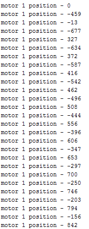
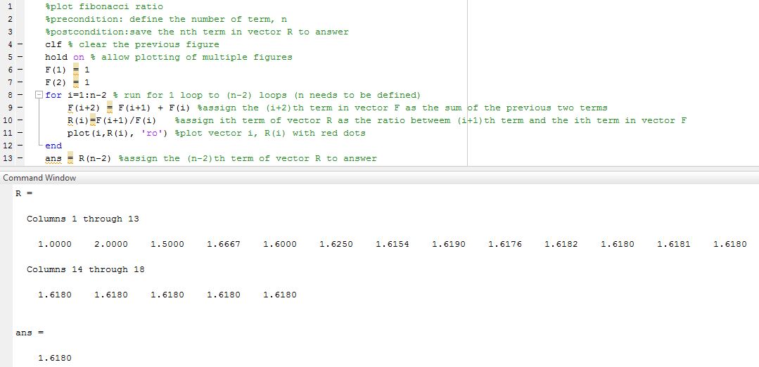


FIBONACCI RATIO

This exercise is a continuation of the one of above it and asks us to graph the ratio of F(i+1)/F(i). We made slight revisions in the names of our functions and how we numbered our loops and then we added in lines 10 and 11 to achieve our end result.


plot of i v. R(i)


BASEBALL

For this exercise, we were tasked with finding the angle of the baseball being hit off the bat that would give us the largest horizontal distance. We were given a code to add on to which made things a lot easier. The first thing we did was to plug in random angles to get a better sense of what was going on. We came to the conclusion that the appropriate angle would be around 45 degrees. Then came the hard part. After a lot of trial and error, we ended up finding that the angle that would produce the biggest horizontal displacement was 44.


plot of x displacement v. y displacement for all angle values


Sunday, March 27, 2016

SciBorgs Part 4 – Proportion Control

Now that we've gotten a pretty good on handle on Bang Bang control, Amy introduced us to proportional control. Instead of an all on or all of system, proportional control allows us access to a whole range of intermediate settings.

GoStraight

For the GoStraight code based on proportional values, we based the speed of the motors off of the difference in encoder values.

We knew we wanted our speed, if there was no error, to be at 160 because 160 is roughly halfway between 70 and 255. In doing this, there would be enough "room" for the motor value to fluctuate without hitting the bounds of 70 or 255, or worse going negative.

Through some trial and error and the help of print lines and the monitor, we were able to find a reasonable constant to be multiplied to the error such that there would be a visible fluctuation in speed.

In this scenario, I personally prefer using bang bang code over proportion control because I felt that the bang bang code is, conceptually, less complicated. Proportional control requires a carefully thought out equation and some trial and error, whereas the bang bang code only requires you to have a basic understanding of the feedback and control system involved. The proportional control code is more sophisticated than the bang bang control and in theory, should produce a smoother straight line path, but it isn't very noticeable.


10Feet

For the 10 feet proportional code, we based the speed of the SciBorg off the distance away from the 10 feet destination. The further the SciBorg is from the 10 feet mark the faster it goes. The closer it gets, the slower it goes, until it should theoretically stop right at the 10 feet mark.

We found that this kind of code works more poorly when the SciBorg is running on surfaces with more friction. For example, the SciBorg was extremely off the mark when it was driving up the ramp because it became really hard for the SciBorg to drive off the last few inches when it had such a small motor value.

When the SciBorg ran down the ramp, the slower speed didn't prevent the SciBorg from reaching the 10 foot mark, but instead, we saw that it propelled the SciBorg past the 10 feet mark. This occured since the force of gravity is now pulling the SciBorg in the same direction as it's momentum, which then also decreases the effects of the force of friction.

When it comes to traveling across inclines, it is best to stick with bang bang control code instead of proportional code.


The SciBorg made it <1cm away from the 10ft mark!


TheSciBorg didn't fare as well on the carpet


FollowOtherSciBorgs

For the proportional follow SciBorg code, we based the speed of the SciBorg's motors off the distance between it and either the Delrin in front of it or the SciBorg in front of it. To figure out the correct constant, we took advantage of the slope equation. We didn't want the SciBorg to get any close to the object in front of it when the ultra sonic sensor produced a value of 13, so we need the speed to be stopping speed, 70 at 13. At a reasonably far distance away, we wanted the SciBorg to be at max speed, 255. So we just set up the equations 13A + K = 70 and 76A +  K = 255 and subtracted one equation from the other in order to solve for A, which we then used to find K.

We did use a bit of bang bang, but it's not really necessary. On the occasion that our SciBorg is further from the object in front than at the value we set, instead of trying to run at a speed of 265 or 300, it defaults back to 255. This doesn't really seem necessary since it should just run at max speed regardless of this line of code, but just in case, we kept this line in.

We found that using this code versus using the bang bang code didn't really make too much of a difference.


FollowPath

For the follow path proportional code, we decided to base the speed of the motors off of the SciBorg's distance from the tape. This one is a little more difficult than the other codes because we had to figure out a way to have only one motor at running speed at a given time and be able to switch without using a bang bang code.

To do this we needed to have two separate equations denoting the respective speeds of the motor. One equation needs to subtract the product of the constant and the sensor value, while the other needs to add to the product, in order to get the alternating speeds. This took a lot more plugging and chugging of data using a similar equations to the one in the above code.

Overall, proportional code requires a little more trial and error and attention to sensor values, but it takes less lines of code than bang bang control and, as you can in the video, it allows the SciBorg to travel more smoothly!


Sunday, March 13, 2016

Real Word Feedback/Control Systems

In our everyday lives we encounter a plethora of feedback/control systems. In this blog post, I will examine four of such everyday systems that we experience while on the road.

Pedestrian Crosswalks

According to the CDC(the Center of Disease Control and Prevention), in 2013, 4,735 pedestrians were killed in traffic accidents in the US. Many of these accidents took place during the evening when it's harder for drivers to see pedestrians at crosswalks. This feedback and control system, which has been implemented in a few cities, can help to seriously decrease these numbers.

Either a force sensor is placed underneath the crosswalk or a push button is placed on a nearby lamppost. The sensing mechanism, force sensor or push button, then relays a message to the control center. This is probably done with some form of circuitry. When the computer/program registers that there is a person waiting to cross the street, the lights around the crosswalk and on nearby posts will light up and flash to inform drivers that a person is crossing, the actuator part of the system. In the case of using a force sensor, the system is intelligent enough to decipher the difference between a bird landing on the crosswalk versus a human being.

This simple feedback and control system is a really helpful way to decrease the number of pedestrian related incidents. In addition, as you can see in the above photo, this process is powered by solar power and hence is self sustainable and doesn't need additional power from a power grid. I think the whole design and concept of this system is really intelligent. Especially in the case of the force sensor, this system makes crossing the street especially safer for children, the elderly, and those handicapped in any way.

Traffic Light Sensors

This feedback and control system works similarly to the one above. This system is especially noticeable in the early morning of cities roads, at three way intersections, or at long stretches of road in order to control the speed of cars. This system does a really good job of easing possible traffic congestion. It works by using a force sensor placed before the crosswalk. In this way, the control center of the system is able to recognize that a car has stopped at an intersection.

The control  computation of this system is intelligent enough that is able to recognize the difference between a person standing in the middle of the street versus a car. This does beg the question of whether the sensor will be able to register a bicyclist... Once the system has registered that there is a car waiting at the intersection, the traffic signal will then turn green allowing the car to go through the intersection. If there is no car, the traffic signal usually defaults to red for the smaller road.

How specifically this system works depends on the specific scenario. As I stated earlier this sort of system is easily application in many traffic light intersections/stretches of road.

In the case of a long stretch of road, the light turns to red if it doesn't sense a car before a certain determined amount of time. This then also forces cars to slow down their speed because they are forced to stop every so often when they otherwise wouldn't need to.

In the case of a smaller road intersecting a larger street, this sort of light system helps to ease traffic congestion, by minimizing the amount of time cars on the larger road have to stop at a red light. If there's rarely any cars coming out of that intersection, why cause a delay on the larger street for no reason.

Lamps on the Side of the Road

The many lamps on campus and those on the side of the road are off during the day on turn on at night. Usually these lamps will have a light sensor, in the form of a photo resistor, on top of them that determine when it is dark enough outside for the lamp to turn on. This photo resistor is usually placed inside a simple circuit with a relay that toggles the light on or off depending on the light level.

We know however, how common it is for a lamp to not work properly. This error, the lamp begin on during the day or not turning on at night is usually an issue with a malfunctioning light sensor or a burned out bulb.

However, the simplicity of this circuit means it is pretty easy to maintain and relatively low cost. This is far more efficient than having a time based lamp as sunset/sunrise changes day by day.


Collision Avoidance Systems

To finish off our theme of feedback and control systems on the road, let's look at the collision avoidance system in cars.

This system usually uses radars, and sometimes lasers and cameras, to determine how far the car is from anything in front of/near it (e.g. a person,  another car, etc.). If the radar returns data suggesting something is too close, the system will then provide a warning to the driver, usually in the form of beeping, and either automatically brakes the car and/or steers the car. Which of the later the system does, depends on the speed of the car. If the car is too close and driving too fast to break in time, the system will then swerve.

In a study 2016 by the Insurance Institute for Highway Safety, the IIHS found that automatic braking systems reduced rear-end crashes by about 40%. That's a pretty significant number. However, this sort of technology is still relatively new and as a result hasn't been perfected. As such, it would be unwise to rely heavily on these systems. Further, I'm not sure whether the system will be able to tell the difference between a box on the road and a rolling ball that a child is chasing after. I'm sure that with further technological advances, collision avoidance systems have the potential of being extremely reliable and something self driving cars will rely heavily on.

Here are a few car commercials advertising emergency warning/brake systems:


Saturday, March 12, 2016

SciBorgs part 3

This activity is a continuation of what we did during SciBorgs part 2. Another assignment that we had to code was for our SciBorgs to follow the SciBorg in front of it. This wasn't very difficult; my partner and I decided to use if else statements given the value from the ultrasonic sensor to determine the speed of our SciBorg. Another idea Amy had was to have the speed of the SciBorg be a proportional to the ultrasonic sensor value, so that the line of code would read: m1.SetFixedDrive( someConstant * value +/- someUknownValue). This is a really cool idea, but would take a lot more experimenting to get right.


Here's a video of SciBorg following another SciBorg. Thanks again to Jennifer and Rachel who let us borrow their robot for the video! Our robot is the blue one in the back.


Friday, March 11, 2016

SciBorgs Part2

In our further explorations of SciBorgs, we learned more about the various sensors available to us –– Encoders, Touch Switches, Light Sensors, and Ultrasonic Sensors. During our earlier explorations, we learned that using time to drive the SciBorg 10 feet wasn't very accurate, so this week, we looked at whether any of the sensors now available to us would be more helpful.

MotorEncoder

We were initially given a code to look at, so that we could get an understanding of how encoders could be useful to us. Looking at the encoder values printed, we saw that if the SciBorg goes forward for 1 second and backwards for 1 second, the encoder value doesn't go to zero. This tells us that the distance traveled, going backwards vs. going forwards, was not the same. Instead, the numbers began to gradually increase (see the photo to the right).

We had a few ideas of what could the be the cause of this discrepancy. We thought that the delay may be caused by a non instantaneous switch from full speed forward to full speed in reverse. It could also be caused by a difference in the friction of the wheels or by the fact that one of the motors is slightly weaker than the other.

In order to get our SciBorg to travel a more accurate 10 feet before stopping, we used our encoder values and a bit of math. We initially created a while loop for as long as the encoder value was less than an arbitrary number, we said 3000. Then we had the SciBorg move along a straight line and measured the distance traveled, 27in. From there, we drew a proportion to calculate the necessary encoder value for the SciBorg to reach 120 inches. We found this to be 1333 1/3. We decided to use 13400 and found that with the encoders, we ended pretty much exactly on the 10 foot line! We found that using Encoders gave us a much more accurate result, as compared to using time.


The first code:


Our adapted 10 feet code:


Touch_Switch_SciBorg_Front

The touch switch worked pretty well and was pretty straightforward. We used the first code to get an idea of how to use a touch switch and to make sure that it was working properly – print unpressed when unpressed, and printing pressed when pressed.

From there, we edited the original if statement so that it would drive forward if unpressed and stop when it was pressed by the delrin board at the end of the 10 foot path. We found that the touch switch worked pretty well – it stopped at the 10 foot mark because that's were we put the board.


The first code:
The updated 10 feet code:


LightSensorNXT


The next sensor we looked at was the light sensor. Using the provided code, we found the the light sensor gave us scaled values between 0 and 100. The lower end of the spectrum was for darker surfaces and the higher end was for lighter surfaces. My partner and I found that the light sensor gave pretty accurate light readings of the surface it hovered over. This is true, unless the surface is reflective, in which case, it read the reflected light values. We also found that turning on the LED light negatively impacted the sensor value because it made everything appear bright. This was at least true for us because we needed to have the light sensor hovering above the ground. Speaking of such, we found that 1/4in or 7/10cm was a pretty good distance for the sensor to work properly. Taking that into consideration, we decided to attach a light sensor onto a conveniently placed axle.


Ultrasonic_sensor

The fourth sensor that we worked with was the ultrasonic sensor. The sensor works by shooting off sound waves and recording the time it takes for the sound to bounce back. When we used our first code to test values, we found the ultrasonic sensor gave us values of 11 when the delrin board was placed in front of the SciBorg.

Editing the code so that it would drive the SciBorg 10 feet and stop in front of the delrin board, we got a pretty decent reading. We found that the SciBorg stopped approximately 2in/5cm from the 10 feet mark. This is still significantly better than basing the distance off of time!

With some further experimenting, we found that the ultrasonic sensor works well against large flat surfaces, but not so well against table/chair/wheelchair legs. The object also has be in the sensor's direct line of sight sound. All in all, the sonar works decently well, but doesn't work for most circumstances.


The first code:
The updated 10 feet code:


StraightBangBang

For this assignment, we needed to fix a problem that has been plaguing us since our first day of using arduinos – serving SciBorgs. This code implements the usage of encoders in a bang bang format. If the left encoder value is larger than the right encoder value, the SciBorg will make a gentle right turn and vice versa for the opposite scenario.

In our experimentation, we found that the SciBorg did okay on the lab floor, but it still veered a bit. We didn't have a ton of time to calibrate the speed of the gentle turns, so maybe this is just because we didn't find the optimal motor turn speeds. The SciBorg did a little better on the carpet, so maybe the friction of the carpet helped to decrease discrepancy in the motor speeds. Surprisingly, our SciBorg did the best while going up a ramp and was the worse at going down the ramp. Our Sciborg made it all the way up the 10 feet ramp! Going down was a whole other story, it was unable to make it all the way down without falling off the side. Hmm..... maybe there's some sort of slippage occurring during the descent...


FollowLine

We had a lot of ideas when it came to the what to do with the path follower code – many of these implemented some sort of searching function in which the SciBorg would need to search for where the line turned. Some of these ideas were definitely more complicated than others and more clunky than others.

One idea I originally had was for the SciBorg to do a 90 degree pivot and than slowly sweep to the left in search of the curve. But, this would be extremely inelegant. Amy had an idea in which the SciBorg would make various turns in a search function. But this similarly did not end up working out.

At the end of the day, we found that we were overthinking the code. Returning to an earlier simpler version of an idea, with some tweaking, we were able to have the SciBorg successfully follow the path. We created another bang bang scenario in which the SciBorg would move forward if the light sensor read a value associated with a white line, the SciBorg would make a gentle right turn, if it read a value at the edge of the strip, and would make a gentle left turn if it read brown, the color of the board.


Here's a video of our SciBorg following along a white path.

It's a little slow, but as we all know pretty well, slow and steady wins the race! (Although, we had a little more time to work on this, we would just increase the motor speed and that should make the SciBorg go faster) Also, we found that the SciBorg sometime struggled with making turns on the tape – increasing the speed should also help with this.

http://www.mcs.uvawise.edu/rjh7g/rh/farks/farks_fall_2010/Slow_and_Steady_Wins_the_Race.jpg